OSLR (Optimized Link-State Routing): Difference between revisions
No edit summary |
|||
| (25 intermediate revisions by the same user not shown) | |||
| Line 1: | Line 1: | ||
==Was ist OLSR ?== |
|||
=Potential causes for packet loss in RoofNet= |
|||
Optimized Link State Routing ist ein Routingprotokoll für mobile Ad-hoc-Netze, das eine an die Anforderungen eines |
|||
Many of the existing routing algorithms rely on the assumption, that the neighbor abstraction holds. This is certainly true as far as wired networks are concerned. In the research community there is no consensus on whether or not it is also true for wireless networks. |
|||
mobilen drahtlosen LANs angepasste Version des Link State Routing darstellt. Es wurde von der IETF unter RFC 3626 standardisiert. |
|||
Bei diesem verteilten flexiblen Routing verfahren ist allen Routern die vollständige Netztopologie bekannt, sodass sie von Fall zu Fall den kürzesten Weg zum Ziel festlegen können. Als proaktives Routingprotokoll hält es die dafür benötigten Informationen jederzeit bereit. |
|||
==Arbeitsweise== |
|||
If it were true, it would imply, that an arbitrary pair of nodes is either able to communicate with each other or not at all. We therefore could expect the loss rates to be either very low or very high depending on the concerned node pair. |
|||
Without claiming general validity for all kinds of wireless networks, the experiments show, that the neighbor abstraction does not hold for RoofNet. One of the experiments revealed a surprising pattern of loss rates for this particular network. Appearently in RoofNet intermediate loss rates are the common case. As the graphic below shows, the majority of the nodes, that can communicate, exhibit intermediate loss rates, designating the nodes with very high and very low loss rates to be the marginal cases. |
|||
Topologieentdeckung erfolgt bei OLSR über zwei Arten von Nachrichten: ''HELLO''- und ''Topology-Control (TC)-Nachrichten''. HELLO-Nachrichten dienen zum Link Sensing, zur Nachbarentdeckung und zur Mitteilung der MPR-Wahl. Die TC-Nachrichten dienen dazu, die so gewonnenen Informationen über mögliche Verbindungen im Netz zu verteilen.<br/> |
|||
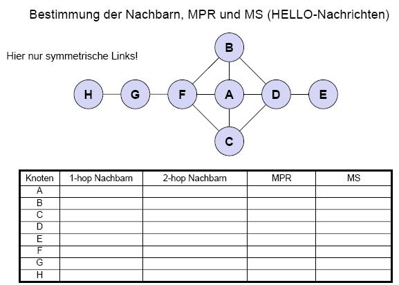
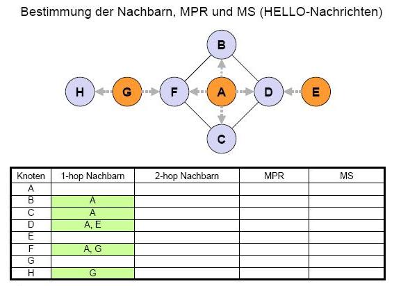
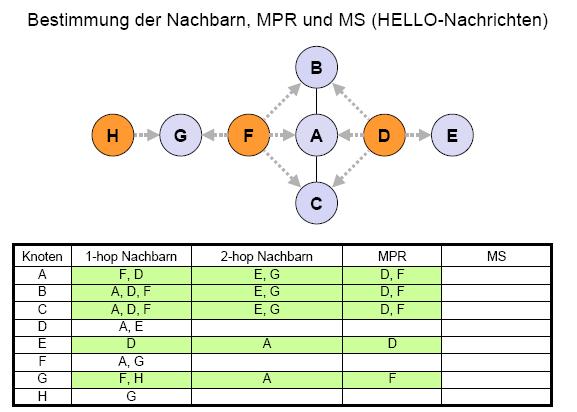
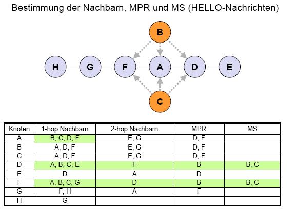
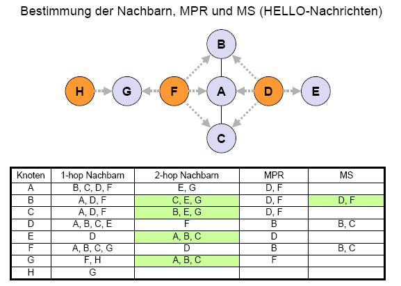
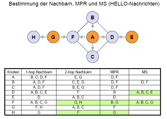
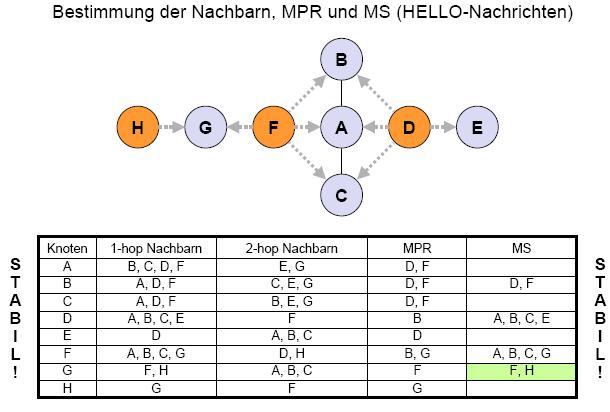
Ein im Netz teilnehmendes Gerät (Knoten) entdeckt seine 1-Hop- und 2-Hop-Nachbarn über die periodisch verschickten HELLO-Nachrichten. Diese enthalten die IP-Adressen der bereits |
|||
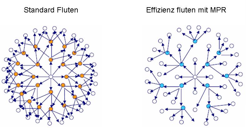
bekannten 1-Hop-Nachbarn sowie den Status der Verbindung zu ihnen und werden nicht weitergeleitet. Aus seinen 1-Hop-Nachbarn wählt jeder Knoten ''Multipoint Relays (MPRs)'', so dass er über sie jeden seiner 2-Hop-Nachbarn erreichen kann. Die MPRs sind die Knoten, die Broadcast-Nachrichten weiterleiten, was das Fluten effizienter macht. Sie sind es auch, die die TC-Nachrichten erstellen, die eine Liste mindestens der Knoten enthalten, von denen sie als MPRs gewählt wurden, so dass für jeden Knoten mindestens eine Möglichkeit bekannt ist, wie er erreicht werden kann. Diese TC-Nachrichten werden im gesamten Netzwerk verteilt. Auf diese Weise erhält jeder Knoten eine Vorstellung des Netzwerkes und kann Routingtabellen erstellen. |
|||
{|width="100%" border="0" |
{|width="100%" border="0" |
||
|- |
|- |
||
|[[Image:Fluten.JPG|thumb|center|600px|Fluten der TC-Nachrichten]] |
|||
|[[Image:Fig4.jpg|thumb|center|400px|The distribution of delivery probabilities in RoofNet. The figure shows only the pairs of nodes, that managed to exchange at least one packet during the experiment.]] |
|||
|- |
|- |
||
|} |
|} |
||
Ablauf in 5 Schritten: |
|||
The question arising from this result is how this particular pattern can be explained. While searching for the answers to this question the researchers investigated among others the following hypotheses as potential causes for this fact: |
|||
*Suchen von Nachbarknoten |
|||
* The effects of node proximity |
|||
**jeder Knoten sendet periodisch so genannte HELLO-Pakete |
|||
* The effects of signal-to-noise ratio |
|||
**Multipoint relay bestimmen |
|||
* The effects of transmit bitrate |
|||
*Messen der Distanzen zu den Nachbarn |
|||
* The effects of multi-path fading |
|||
**ein Knoten sendet Echo-Pakete an alle Nachbarn, die diese sofort beantworten müssen |
|||
**die Zeit, die zwischen Echo-Paket und Antwort vergeht, kann als Distanz benutzt werden |
|||
In the following sections a brief summary of the results for each hypothesis will be given. |
|||
*Erzeugen eines Kontrollpakets (engl.: Topology Control Message, TC), |
|||
*Senden des Kontrollpakets an alle Knoten des Netzwerks (Multipoint relay) |
|||
==Effects of node proximity on loss rates== |
|||
*Erstellen eines Abbilds der Netzwerktopologie |
|||
Trying to explain the loss rate pattern as a function of node distance at the first glance seems to be a very promising approach. But the data obtained from the experiments shows that node proximity is a very weak predictor for loss rates. The following three graphics strengthen the results. They show the delivery probabilities of three sender nodes to all other RoofNet nodes. The bigger the diameter of a circle is, the bigger is the delivery probability to the corresponding RoofNet node. |
|||
==Beispiel== |
|||
{|width="100%" border="0" |
{|width="100%" border="0" |
||
|- |
|- |
||
|[[Image:Bei1.JPG|thumb|left|500px|]] |
|||
|width="50%"|[[Image:Fig5-2.jpg|thumb|center|300px|]] |
|||
|- |
|- |
||
|width="50%" colspan="2"|[[Image:Fig5-3.jpg|thumb|center|300px|]] |
|||
|} |
|} |
||
For inter node distance to be the explaination for the distribution of the loss rates, there should be a correlation between the distance and the resulting delivery probability. One could expect the recieved signal to be consistently weaker, the bigger the distance to the source node is. |
|||
The surprising fact is, that this is not the case. Inter node distance certainly determines the delivery probability to some extent, but the correlation is not consistent. As the graphics show, even very small variations of the sender position have tremendous effects on the resulting pattern of delivery probabilities. If node proximity was the decisive factor, we would certainly see a stronger correlation. |
|||
==The effect of signal-to-noise ratio== |
|||
The predominance of intermediate loss rates could be due to marginal signal-to-noise values for the majority of the nodes. The 802.11 cards used in RoofNet are based on the Prism Chipset. According to the Prism specification the range of signal-to-noise values, which result in a packet error rate between 10\% and 90\%, is 3db wide. |
|||
In order to blame the intermediate delivery probabilities on the signal-to-noise ratio, it should be possible to find most of the node pairs in RoofNet in this narrow range. |
|||
But again the experiments reveal, that reality looks different. As the following graphic shows, the range of signal-to-noise ratios is much wider than expected. |
|||
{|width="100%" border="0" |
{|width="100%" border="0" |
||
|- |
|- |
||
|[[Image:Bei2.JPG|thumb|left|500px|]] |
|||
|[[Image:Fig13.jpg|thumb|center|400px|Distribution of the average signal-to-noise values for the sender-reciever pairs.]] |
|||
|- |
|- |
||
|} |
|} |
||
The graphic implies, that signal-to-noise ratio is not a decisive factor for the distribution of loss rates. |
|||
==The effect of transmit bitrate== |
|||
As far as transmit bitrate is concerned, there are a couple of interesting implications, that can be drawn from the experiments. These experiments show, that the transmit bitrate that provides optimum performance in terms of throughput, is not characterized by the minimum loss rate. On the contrary, the optimum bitrate of 11 Mbps exhibits a significant loss rate. The results of a corresponding experiment are visualised in the following figures. |
|||
{|width="100%" border="0" |
{|width="100%" border="0" |
||
|- |
|- |
||
|[[Image: |
|[[Image:Bei3.JPG|thumb|left|500px|]] |
||
|- |
|||
||[[Image:Fig17.jpg|thumb|center|350px|The throughput in RoofNet at different bitrates. Data is ordered by the throughput at 11 Mbps.]] |
|||
|} |
|||
{|width="100%" border="0" |
|||
|- |
|||
|[[Image:Bei4.JPG|thumb|left|500px|]] |
|||
|- |
|||
|} |
|||
{|width="100%" border="0" |
|||
|- |
|||
|[[Image:Bei5.JPG|thumb|left|500px|]] |
|||
|- |
|||
|} |
|||
{|width="100%" border="0" |
|||
|- |
|||
|[[Image:Bei6.JPG|thumb|left|500px|]] |
|||
|- |
|||
|} |
|||
{|width="100%" border="0" |
|||
|- |
|||
|[[Image:Bei7.JPG|thumb|left|500px|]] |
|||
|- |
|- |
||
|} |
|} |
||
==Links== |
|||
These results suggest to change the policy of bitrate selection algorithms: Instead of reducing the bitrate immediately, when transmission errors occur, a bitrate selection algorithm for wireless networks should wait, because despite of the errors and the nessecary retransmissions a higher bitrate performs significantly better than a lower one at its optimum. |
|||
[http://www.dpunkt.de/mobile/code/olsr.html Java Implementation] |
|||
==The effect of multi-path fading== |
|||
The fact, that so many node pairs have intermediate delivery probabilities in RoofNet, is probably due to the phenomenon of multi-path fading. From all of the experiments, that were performed in this context, the one investigating the effect of multi-path fading led by far to the strongest results. |
|||
[http://hipercom.inria.fr/olsr/mpr-flooding.html Flash Implementation] |
|||
The challenge, that multi-path-fading poses to the manufacturers of 802.11 cards is illustrated in the following figure. |
|||
Latest revision as of 17:05, 17 July 2007
Was ist OLSR ?
Optimized Link State Routing ist ein Routingprotokoll für mobile Ad-hoc-Netze, das eine an die Anforderungen eines mobilen drahtlosen LANs angepasste Version des Link State Routing darstellt. Es wurde von der IETF unter RFC 3626 standardisiert. Bei diesem verteilten flexiblen Routing verfahren ist allen Routern die vollständige Netztopologie bekannt, sodass sie von Fall zu Fall den kürzesten Weg zum Ziel festlegen können. Als proaktives Routingprotokoll hält es die dafür benötigten Informationen jederzeit bereit.
Arbeitsweise
Topologieentdeckung erfolgt bei OLSR über zwei Arten von Nachrichten: HELLO- und Topology-Control (TC)-Nachrichten. HELLO-Nachrichten dienen zum Link Sensing, zur Nachbarentdeckung und zur Mitteilung der MPR-Wahl. Die TC-Nachrichten dienen dazu, die so gewonnenen Informationen über mögliche Verbindungen im Netz zu verteilen.
Ein im Netz teilnehmendes Gerät (Knoten) entdeckt seine 1-Hop- und 2-Hop-Nachbarn über die periodisch verschickten HELLO-Nachrichten. Diese enthalten die IP-Adressen der bereits
bekannten 1-Hop-Nachbarn sowie den Status der Verbindung zu ihnen und werden nicht weitergeleitet. Aus seinen 1-Hop-Nachbarn wählt jeder Knoten Multipoint Relays (MPRs), so dass er über sie jeden seiner 2-Hop-Nachbarn erreichen kann. Die MPRs sind die Knoten, die Broadcast-Nachrichten weiterleiten, was das Fluten effizienter macht. Sie sind es auch, die die TC-Nachrichten erstellen, die eine Liste mindestens der Knoten enthalten, von denen sie als MPRs gewählt wurden, so dass für jeden Knoten mindestens eine Möglichkeit bekannt ist, wie er erreicht werden kann. Diese TC-Nachrichten werden im gesamten Netzwerk verteilt. Auf diese Weise erhält jeder Knoten eine Vorstellung des Netzwerkes und kann Routingtabellen erstellen.
 |
Ablauf in 5 Schritten:
- Suchen von Nachbarknoten
- jeder Knoten sendet periodisch so genannte HELLO-Pakete
- Multipoint relay bestimmen
- Messen der Distanzen zu den Nachbarn
- ein Knoten sendet Echo-Pakete an alle Nachbarn, die diese sofort beantworten müssen
- die Zeit, die zwischen Echo-Paket und Antwort vergeht, kann als Distanz benutzt werden
- Erzeugen eines Kontrollpakets (engl.: Topology Control Message, TC),
- Senden des Kontrollpakets an alle Knoten des Netzwerks (Multipoint relay)
- Erstellen eines Abbilds der Netzwerktopologie
Beispiel
 |
 |
 |
 |
 |
 |
 |