Brn.Phy: Difference between revisions
| (11 intermediate revisions by the same user not shown) | |||
| Line 1: | Line 1: | ||
Details about the physical layers in Brn.Sim. Tbd. |
Details about the physical layers in Brn.Sim. Tbd. |
||
= |
= Propagation = |
||
== |
== Large Scale Path Loss == |
||
Currently Brn.Sim supports the path loss models FreeSpace, TwoRay and LogDistance. |
|||
=== Free Space Path Loss === |
|||
The model is shipped with vanilla JiST/SWANS. It is a special case of the Log-Distance Model with path loss exponent 2.0. |
|||
=== Two Ray Path Loss === |
|||
The model is shipped with vanilla JiST/SWANS. |
|||
=== Log-Distance based Path Loss === |
|||
[[Image:dist-snr-simplepathloss-3.5.png]] |
[[Image:dist-snr-simplepathloss-3.5.png]] |
||
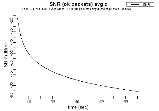
Pathloss using the log-distance based model (see Goldsmith Wireless Communication p. 40) and path loss exponent 3.5 (1sec == 1m). |
Pathloss using the log-distance based model (see Goldsmith Wireless Communication p. 40) and path loss exponent 3.5 (1sec == 1m). |
||
== Shadow Fading == |
|||
Brn.Sim supports log-normal shadowing to account for possibly time-varying obstacles in the propagation path. The model was derived from [http://www.isi.edu/nsnam/ns/ ns-2] and [http://www.eg.bucknell.edu/swan/ SWAN]. The shadowing variability can be changed by modifying the standard deviation of the underlaying normal distribution. Furthermore, it supports different types of timely correlations. When setting the coherence time to 0, a new shadowing value is realized for each transmission (the ns-2 approach). By setting the coherence time to a fixed positive value, the shadowing coefficient remains constant for the specified duration, before it is realized anew. Additionally there is the possibility to use an exponential distribution for coherence times. |
|||
In Brn.Sim, shadowing is realized as a composite path loss model which can be used with any other path loss model. |
|||
== Small Scale Fading == |
|||
JiST/SWANS comes with probabilistic models for Rayleigh and Rician Fading. Additionally we realized the Rician fading model from Punnoose and Jakes model. |
|||
=== Punnoose Rician Fading === |
|||
The Punnoose Model uses a pre-calculated fading realization with reasonable statistical distribution and timely correlation and only adjusts the variability (the Rician K factor) and evolution speed (via maximum velocity, i.e. doppler). Details can be found in [http://scholar.google.com/scholar?q=Punnoose+%22Efficient+Simulation+of+Ricean+Fading+within+a+Packet+Simulator%22 Punnoose "Efficient Simulation of Ricean Fading within a Packet Simulator"]. Furthermore, we applied [http://www.winlab.rutgers.edu/~zhibinwu/html/ns_fading_error.html this patch]. |
|||
=== Jakes Model === |
|||
We ported Jakes model from [http://www.dei.unipd.it/wdyn/?IDsezione=5529] to Brn.Sim. |
|||
== Propagation Delay == |
|||
Tbd. |
|||
== Implementation Details == |
|||
=== Hierarchical Binning === |
|||
JiST/SWANS use spatial binning to improve simulation performance, similar to SNS ([http://www.cs.cornell.edu/people/egs/sns/ STAGED NETWORK SIMULATOR]). The idea is to partition the simulation area into bins. If a node at position X emits a signal, that a bin is visited only if the signal strength at a defined reference location (the location inside the bin nearest to X) exceeds a certain threshold. Thus, spatial binning prunes all bins in which none of the nodes would receive the signal. |
|||
However, there is a problem with shadowing and fading, because signal strength and distance are not monotonically any more. So there is a probability that the binning prunes bins because of severe fading at the reference location, whereas other nodes within the bin would receive the signal. We address this problem by adding a fading margin to the reference signal strength calculation. In detail, we use the 95. percentile for log-normal fading and the 99. percentile for Rician fading. |
|||
= Receiver Models = |
|||
== SNR based Receiver == |
|||
The SNR model defines two thresholds: a sensing and a receiving threashold. If the SNR of the incoming packet is above the receiving (sensing) threshold, the packet is received (sensed). The thresholds are generally different for different bit rates and they are also hardware dependent. |
|||
[[Image:dist-per-simplepathloss-3.5.png]] |
|||
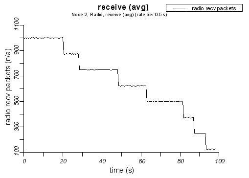
In this example a node transmits 2000 frames per second, using all available IEEE 802.11g bit rates. A second node is placed near the sender and moves away with 1 m/s. We are again using the log-distance pathloss model with exponent 3.5. While the receiver moves away the SNR of received packets also decrease. Eventually it drops below the threshold for the used bit rate and the frame is not received. Instead the receiver only senses the frame. While moving further away the received SNR eventually drops below the sensing threshold (see next figure). Note that there is only one sensing threshold per receiver, but our IEEE 802.11g transmitter uses different power levels for different bit rates. |
|||
[[Image:dist-sens-simplepathloss-3.5.png]] |
|||
== BER based Receiver == |
|||
The BER receiver model calculates Bit and Packet Error Rates, which are used as probability whether a frame is received without error. Frame reception becomes a stochastic process depending on the used modulation and coding scheme (i.e. bit rate), the SNR (distance) and number of bits. |
|||
[[Image:dist-per-simplepathloss-3.5-ber.png]] |
|||
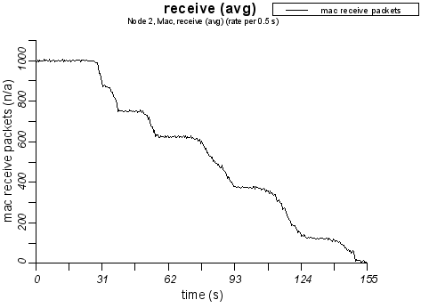
Both figures show the number of received and sensed frames for the BER receiver in the same scenario described in the previous section. Note that the thresholds of the SNR receiver caused sharp fall-offs: At a certain point the PER for a given bit rate changed abruptly from 0 to 1. Using the BER receiver we now have soft transition. Note further that the sensing range is larger compared to the SNR receiver, because the model still uses thresholds for preamble detection. This may not be very realistic and will likely be changed in future versions. |
|||
[[Image:dist-sens-simplepathloss-3.5-ber.png]] |
|||
== Diversity Transceiver == |
|||
Tbd. |
|||
= References = |
|||
* Goldsmith Wireless Communication |
|||
* Paper yans physical layer |
|||
Latest revision as of 13:23, 16 March 2008
Details about the physical layers in Brn.Sim. Tbd.
Propagation
Large Scale Path Loss
Currently Brn.Sim supports the path loss models FreeSpace, TwoRay and LogDistance.
Free Space Path Loss
The model is shipped with vanilla JiST/SWANS. It is a special case of the Log-Distance Model with path loss exponent 2.0.
Two Ray Path Loss
The model is shipped with vanilla JiST/SWANS.
Log-Distance based Path Loss
Pathloss using the log-distance based model (see Goldsmith Wireless Communication p. 40) and path loss exponent 3.5 (1sec == 1m).
Shadow Fading
Brn.Sim supports log-normal shadowing to account for possibly time-varying obstacles in the propagation path. The model was derived from ns-2 and SWAN. The shadowing variability can be changed by modifying the standard deviation of the underlaying normal distribution. Furthermore, it supports different types of timely correlations. When setting the coherence time to 0, a new shadowing value is realized for each transmission (the ns-2 approach). By setting the coherence time to a fixed positive value, the shadowing coefficient remains constant for the specified duration, before it is realized anew. Additionally there is the possibility to use an exponential distribution for coherence times.
In Brn.Sim, shadowing is realized as a composite path loss model which can be used with any other path loss model.
Small Scale Fading
JiST/SWANS comes with probabilistic models for Rayleigh and Rician Fading. Additionally we realized the Rician fading model from Punnoose and Jakes model.
Punnoose Rician Fading
The Punnoose Model uses a pre-calculated fading realization with reasonable statistical distribution and timely correlation and only adjusts the variability (the Rician K factor) and evolution speed (via maximum velocity, i.e. doppler). Details can be found in Punnoose "Efficient Simulation of Ricean Fading within a Packet Simulator". Furthermore, we applied this patch.
Jakes Model
We ported Jakes model from [1] to Brn.Sim.
Propagation Delay
Tbd.
Implementation Details
Hierarchical Binning
JiST/SWANS use spatial binning to improve simulation performance, similar to SNS (STAGED NETWORK SIMULATOR). The idea is to partition the simulation area into bins. If a node at position X emits a signal, that a bin is visited only if the signal strength at a defined reference location (the location inside the bin nearest to X) exceeds a certain threshold. Thus, spatial binning prunes all bins in which none of the nodes would receive the signal.
However, there is a problem with shadowing and fading, because signal strength and distance are not monotonically any more. So there is a probability that the binning prunes bins because of severe fading at the reference location, whereas other nodes within the bin would receive the signal. We address this problem by adding a fading margin to the reference signal strength calculation. In detail, we use the 95. percentile for log-normal fading and the 99. percentile for Rician fading.
Receiver Models
SNR based Receiver
The SNR model defines two thresholds: a sensing and a receiving threashold. If the SNR of the incoming packet is above the receiving (sensing) threshold, the packet is received (sensed). The thresholds are generally different for different bit rates and they are also hardware dependent.
In this example a node transmits 2000 frames per second, using all available IEEE 802.11g bit rates. A second node is placed near the sender and moves away with 1 m/s. We are again using the log-distance pathloss model with exponent 3.5. While the receiver moves away the SNR of received packets also decrease. Eventually it drops below the threshold for the used bit rate and the frame is not received. Instead the receiver only senses the frame. While moving further away the received SNR eventually drops below the sensing threshold (see next figure). Note that there is only one sensing threshold per receiver, but our IEEE 802.11g transmitter uses different power levels for different bit rates.
BER based Receiver
The BER receiver model calculates Bit and Packet Error Rates, which are used as probability whether a frame is received without error. Frame reception becomes a stochastic process depending on the used modulation and coding scheme (i.e. bit rate), the SNR (distance) and number of bits.
Both figures show the number of received and sensed frames for the BER receiver in the same scenario described in the previous section. Note that the thresholds of the SNR receiver caused sharp fall-offs: At a certain point the PER for a given bit rate changed abruptly from 0 to 1. Using the BER receiver we now have soft transition. Note further that the sensing range is larger compared to the SNR receiver, because the model still uses thresholds for preamble detection. This may not be very realistic and will likely be changed in future versions.
Diversity Transceiver
Tbd.
References
- Goldsmith Wireless Communication
- Paper yans physical layer
